
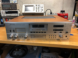
 When the owner of a Realistic STA-2200 Digitally Synthesized AM/FM Stereo Receiver contacted NDF, they had nearly exhausted their repair options. Purchased from an eBay seller, the receiver arrived with severe shipping damage. Other businesses had reportedly called it a lost cause and declined the work. NDF was the last business the customer called.
The description was daunting: the rear of the receiver had buckled into a V shape, and circuit board material had shattered into pieces. The customer believed they had recovered all the fragments. Their request was straightforward: “Could you just get it working?” We accepted the repair challenge, beginning with an inspection to determine what could realistically be recovered.
Assessing the Damage and Establishing a Plan
On the bench, the receiver showed substantial impact damage. The top ventilation grille was dented, and a severe impact near the center of the rear panel had buckled the metalwork. Its condition indicated that the packaging had not provided adequate protection during shipping.
We documented the external damage before inspecting the interior. Inside, the receiver showed typical age-related dust accumulation, along with a shattered speaker-output circuit board. That board became the first priority: before meaningful functional testing could begin, we needed to restore its mechanical integrity and electrical connections.
Our inspection supported attempting a repair, but it did not establish that the rest of the receiver worked. We explained this distinction to the customer and proposed a staged approach: repair the damaged board and its relay, then test the receiver and quote any additional faults discovered.
Rebuilding the Shattered Speaker-Output Board
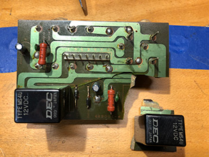 We started with the relay mounted on the damaged board. After removing its cover, we inspected the internal mechanism for impact damage. It appeared intact, and energizing the relay with a bench power supply confirmed that it operated. The damage appeared limited to the cover, which was replaced.
Next came reconstructing the board itself. We fitted the recovered fragments together like a puzzle, carefully matching the broken edges. Once the pieces were positioned, we bonded them with epoxy and allowed the adhesive to cure before restoring the broken electrical connections.
Each interrupted copper trace was bridged with 20-gauge solid-core wire. Wherever practical, the repair wire followed the original trace route rather than taking a shortcut across the board. We also replaced two diodes and two electrolytic capacitors on this assembly. The reconstructed board was then tested before proceeding with reassembly.
Straightening the Chassis Without Causing More Damage
The buckled rear panel required a separate mechanical repair. Rather than straighten it with connectors and assemblies still attached, we removed the items mounted to the affected rear frame. This provided access to the damaged metalwork and reduced the risk of transferring bending forces into other components.
With the frame straightened, we reassembled the rear of the receiver and prepared for initial power-up. It powered on without blowing a fuse, but that was only the first checkpoint. The clock and digitally synthesized tuning were still inoperative.
Testing the Amplifier Independently
To separate the amplifier’s condition from the tuning fault, we selected AUX and applied a 1 kHz test signal to both input channels. The speaker outputs were connected to an 8-ohm, 100-watt dummy load, and we observed both channels with an oscilloscope.
The outputs appeared clean and responded to the controls. This established that the amplifier could pass the applied signal under those test conditions; it was not, by itself, a complete performance characterization. It did give us a sound basis for moving on to the clock and tuning circuitry.
We also spot-checked capacitors, diodes, and resistors. Most checked within specification. Components that produced questionable in-circuit readings were removed and tested again, with replacements made where needed. This avoided treating every questionable in-circuit measurement as proof of a failed part.
Restoring the Clock and PLL Tuning
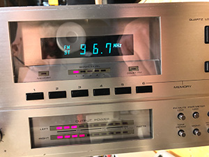 Troubleshooting the clock and phase-locked-loop tuning board revealed a regulator with no output. To investigate further, we supplied 5 VDC downstream of the regulator. The board came to life, providing evidence that its missing supply was a central problem.
We replaced the affected power regulators on the clock and tuning board. AM and FM tuning then operated, and no alignment was needed during this repair. Combined with the earlier amplifier testing, this brought the receiver back to functional operation.
Fabricating Missing Parts and Improving the Appearance
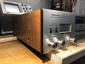 With the electrical repairs complete, we addressed several cosmetic and handling issues. Both end caps were missing from the extruded-aluminum front panel, leaving exposed edges that could catch someone moving the receiver.
We measured the extrusion and created replacement left- and right-hand end caps in CAD. Printed in black ABS, the new parts complemented the receiver’s existing black controls. During installation, we also smoothed raised gouges in the aluminum to improve the faceplate’s appearance.
We straightened the top and bottom ventilation grilles and applied a hard-wax finish to the original walnut cabinet. The result was not a claim of factory-new restoration: some evidence of its history remained. Nevertheless, the receiver looked substantially better, played again, and was returned to a pleased customer.
A Later Power-Supply Failure
Approximately three months later, the customer reported that the receiver had stopped playing in the middle of a song. When it returned to our bench, troubleshooting identified a shorted rectifier module on the power-supply board and a blown protection fuse.
We replaced both rectifier modules. This was a separate fault from the shattered speaker-output board repaired during the initial visit. The customer then requested broader preventive service, explaining that they particularly liked this receiver and wanted to continue using it for as long as possible.
Preventive Service With Informed Expectations
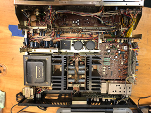 The expanded service included replacing all electrolytic capacitors with modern replacements, using film capacitors in selected positions, and replacing several preamplifier transistors with modern equivalents. The removed parts were more than 45 years old.
We discussed the scope and tradeoffs with the owner before proceeding. Broad component replacement is not the same as repairing a demonstrated individual fault, and modern substitutions should not be presented as a guarantee of unchanged sound. The customer understood that substitutions could affect circuit response and the listening experience.
The Result
After the receiver was returned, the customer reported that it was working well. Their description was, “After many hours play, the sound stage opened up.” That was their listening impression, rather than a measured performance claim.
This project combined circuit-board reconstruction, signal tracing, power-supply diagnosis, chassis repair, and custom part fabrication. The documented repairs restored operation, and the customer’s subsequent report confirmed continued enjoyment after delivery. Long-term reliability beyond that follow-up remains unverified, but a receiver initially dismissed as a lost cause was back in use.
Contact Next Dimension Fabworks today to have your stereo or amplifier repaired today.