
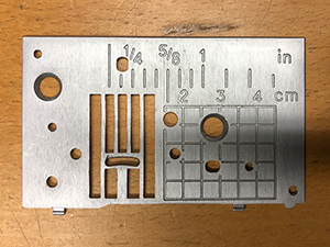
 A small machine component can create a significant operational problem when it interacts with other equipment in an unexpected way. For one Next Dimension Fabworks customer, that component was the metal pressure foot plate on an embroidery machine. When used with magnetic embroidery hoops, the original plate created an unwanted attraction that interfered with the hoop’s movement.
The customer came to us with a practical question: could we duplicate the existing metal plate in plastic? Using the original component as our reference, we measured the part, recreated its geometry in CAD, and refined the design through multiple 3D-printed iterations. The project resulted in three thermoplastic replacement plates—one for each of the customer’s embroidery machines.
The Challenge: An Unwanted Magnetic Interaction
The customer reported that the trouble occurred when the edge of a magnetic embroidery hoop approached the machine’s metal pressure foot plate. The magnets in the hoop attracted the plate, causing the hoop to lurch toward it and bind against it. Instead of moving as intended, the hoop could become caught by that interaction.
This made the original plate the focus of the project. The customer was not asking us to redesign the embroidery machine or modify the magnetic hoops. They wanted a plastic duplicate of the existing component that would preserve its physical configuration while removing the metal plate from that interaction.
Because the customer had three embroidery machines experiencing the same issue, the project also required repeatability. We needed to develop a matching model that could be used to produce a replacement for each machine, rather than treating each plate as a separate custom fabrication job.
Starting With the Original Component
The customer supplied an actual pressure foot plate from the embroidery machine. Having the original part available gave us a direct reference for both the initial measurements and the later comparisons. Rather than interpreting a photograph or estimating dimensions, we could examine and measure the component we were being asked to reproduce.
We used a combination of a ruler and digital caliper to document the plate’s dimensions and features. These measurements provided the foundation for building the replacement model. Particular attention was needed around the pins, where size and placement would become important details during the refinement process.
This stage illustrates an important part of our approach to custom fabrication: start with the physical requirements of the existing part. A replacement needs more than a similar outline. The features that locate it or connect it to other components must also be represented accurately.
Recreating the Plate in CAD
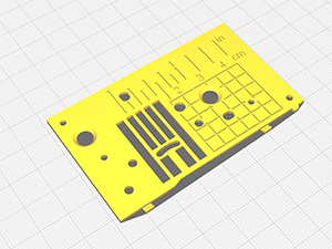 With the measurements collected, we recreated the pressure foot plate in CAD, or computer-aided design software. This converted the physical reference into a digital model that could be used for 3D printing and adjusted as the project progressed.
The objective was to reproduce the customer’s existing component, not introduce unnecessary design changes. The original plate established the geometry we were working toward, while the customer’s request established the intended material change: a thermoplastic replacement for the metal part.
Building a CAD model also gave us a controlled way to make corrections. When a printed feature needed adjustment, we could revise the corresponding geometry in the model and produce another version. That kept the development process tied to specific dimensions rather than relying on improvised alterations to an individual print.
From Digital Model to Physical Prototype
Once the initial model was complete, we 3D printed the first version and compared it with the original metal pressure foot plate. This comparison was an essential part of the work. A model can represent the intended dimensions, but the printed component still needs to be checked against the physical reference.
In this project, the printing process introduced enough dimensional variation that the first print required refinement. The pin size and pin placement were the details that needed further attention. Those features made the difference between a part that broadly resembled the original and one that matched the required geometry.
We used the comparison to guide revisions, then printed the updated model. It took two additional attempts after the first print to achieve the matching pin size and placement described in the project record. Each iteration moved the work forward through a concrete cycle: print, compare, adjust, and print again.
Why the Refinement Process Mattered
The prototype stage was not simply about checking appearance. It was about resolving the differences between the measured original, the digital model, and the physical output of the printer. In this case, the pin details required that extra work before we proceeded with the customer’s set of replacements.
That distinction matters in reverse-engineering projects. Creating a digital version of an existing component is one part of the task; producing a physical duplicate with the required feature dimensions is another. Our work on this plate included both, with the original component remaining the reference throughout the process.
The additional iterations also demonstrate why we do not treat the first print as an automatic finished product. Here, direct comparison identified details that needed correction, and the CAD-to-print workflow gave us a practical way to address them.
Producing Plates for All Three Machines
After refining the model, we 3D printed three thermoplastic pressure foot plates, one for each of the customer’s embroidery machines. The completed digital model provided a common basis for producing the set.
The documented fabrication result was three replacement plates developed from the supplied original, with pin size and placement refined through successive prints. Installation results, long-term wear, and performance during embroidery operation were not independently verified in the information available for this case study. The completed fabrication work should therefore be distinguished from an independently confirmed operational outcome.
Practical Reverse Engineering From Next Dimension Fabworks
This project brings together several capabilities we offer at Next Dimension Fabworks: measuring an existing component, recreating it in CAD, producing physical prototypes, and refining printed geometry through direct comparison. It also shows how those capabilities can be applied to a focused customer request without expanding the scope into a larger machine redesign.
From the original metal plate to a set of three thermoplastic replacements, our contribution was a measured, iterative fabrication process. The result demonstrates our ability to turn a supplied component and a clearly described problem into a custom-manufactured part, while keeping the work grounded in physical reference measurements and documented refinement.
Contact Next Dimension Fabworks today to start your project today.